Types Of Lines In Civil Engineering Drawing
In this article, we will discuss the different Types Of Lines In Civil Engineering Drawing and what they depict. An engineer, designer, or architect would struggle to convey the shape, scale, and interrelation of a complex thing in words.
As a result, drawings have become the worldwide language used by engineers, designers, technicians, and craftsmen to transmit the information required to develop, install, and service industrial items. Lines are a major part of the graphic language used by the engineering industry.
Lines are straight elements with no breadth but unlimited length (magnitude), and they can be found by locating two points that are not in the same location but fall along the line. Straight lines and curved lines are both possible. The shortest distance between two points is a straight line.
It can be drawn in any direction. The actual length of a line is a matter of convenience if it is indefinite and the endpoints are not fixed in length.
If a line’s endpoints are crucial, they must be marked by small, mechanically drawn crossbars, as described by a point in space. Straight and curved lines are said to be parallel if the shortest distance between them remains constant.
| Style/ Thickness | Thick | Thin | |
| Continuous |
|
||
| Dash |
_ _ _ _ _ _ _ _ _ _ _ _ |
_ _ _ _ _ _ _ _ _ _ _ _ _ | |
| Chain |
_______ _______ _______ |
_______ _______ _______ ______ |
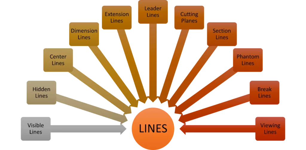
13 Main Types Of Lines
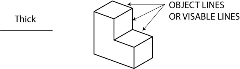
1. Visible/Object Lines
- Dark, thick lines
- They are used to show the outline or contour of an object being drawn.
- They define the features that can be seen in a specific/particular view.
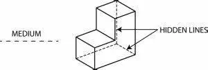
2. Hidden Lines
- Lines that are light, narrow, short, and dashed.
- Displays the outline of a feature that cannot be seen in a specific/particular view.
- They are used to help clarify a feature, however, they can be eliminated if they clog a drawing.
- A dash should always be used to start and end hidden lines, except where a hidden line begins or terminates at a parallel visible or hidden line.
- Dashes should meet in the corners.
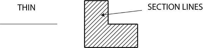
3. Section Lines
- A thin line is drawn at a 45-degree angle.
- In a sectional view, this indicates the material that has been cut through.
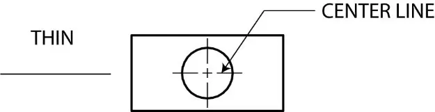
4. Center Lines
- A thin line made up of alternating long and short dashes is used to show the center of round or cylindrical objects, as well as the symmetry of a feature.
- Long dashes should be used to begin and terminate center lines.
- Center lines should intersect by crossing either the long or short dashes and should continue a short distance beyond the object or feature.
- Within a single view, center lines can be joined to represent that two or more features are in the same plane. The center lines should not cross the space between views.
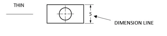
5. Dimension Lines
- Thin lines with arrowheads at the ends that are broken along their length to make room for the dimension number.
- They represent length.
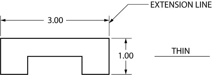
6. Extension Lines
- Thin lines are used to determine the extent of a dimension. It is also possible to use it to demonstrate the extension of a surface to a theoretical intersection.
- Begin 1.5 mm away from the object and work your way out to 3 mm beyond the last dimension. Dimension lines should not be crossed.
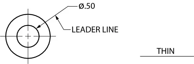
7. Leader Lines
- Thin lines are used to connect a specific note to a feature on a drawing, as well as to direct dimensions, symbols, item numbers, and part numbers.
- Typically drawn at 45, 30, and 60 degrees.
- Has a short shoulder (3-6mm) at one end that begins at the center of the vertical height of the text and a standard dimension arrowhead at the other end that touches the feature.
- Leader lines should not cross one another.
- Leader lines should not be overly long.
- Leader lines should not be vertical or horizontal in orientation.
- Dimension lines, extension lines, and section lines should not be parallel to leader lines.
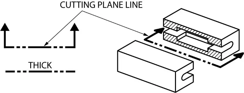
8. Cutting Plane Lines
- A thick broken line with small 90 degree arrowheads
- Indicates where a section is mentally cut in half to better perceive the interior detail.
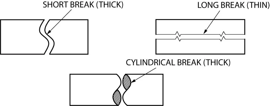
9. Break Lines
Break Lines are used to separate sections for clarity or to shorten a section. There are three types of break lines, each with a distinct line weight:
- Short Break Lines
A thick wavy line used to break the edge or surface of a part to reveal a concealed surface.
- Long Break Lines
Long, thin lines that indicate that the center section of an object has been removed so that it can be drawn on a smaller piece of paper.
- Cylindrical Break Lines.
Thin lines used to depict spherical parts that have been broken in half to better clarify the print or to shorten the object’s length.
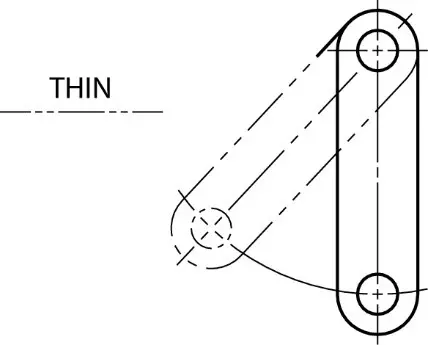
10. Phantom Lines
Phantom Lines are thin lines composed of long dashes alternated with pairs of small dashes. Drawings serve three functions:
- To depict the alternate location of moving parts.
- To demonstrate the relationship between elements that fit together.
- To demonstrate repetitive detail.
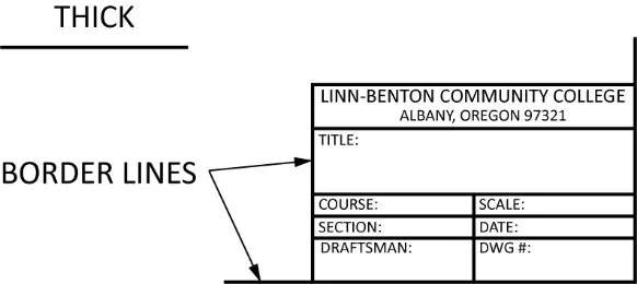
11. Border Lines
Borderlines are thick, continuous lines used to show the drawing’s boundaries or to divide different objects drawn on the same sheet. They are also used to distinguish the title block from the body of the illustration.
12. Arrowheads
- Arrowheads are used to end dimension lines, leader lines, cutting-plane lines, and viewing plane lines.
- They should be three times the length of the width.
- They should all be the same size across the board.
- Because of its clarity, the filled arrowhead is often favored.
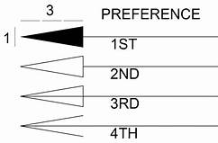
13. Line Precedence
If two lines appear in the same position, the line deemed to be the least relevant is omitted. The following are the lines in order of precedence/importance:
- Cutting plane line
- Visible line
- Hidden line
- Centerline
Conclusion
A line in an engineering drawing isn’t just a line. The various lines each have their own significance. The above-mentioned line types are in accordance with ISO requirements for civil engineering drawing.